Four Bar Linkage
//CAD (SolidWorks)
//motion simulation
Task
Model four bars: a crank, coupler, rocker, and base, each with a unique design. Assemble a four bar linkage with a choice of fastener, run a motion analysis and map the path of motion of the crank. Also, create two drawings, one that depicts the full assembly and one that depicts an exploded view with a properly formatted bill of materials.
Design
First, a unique design for each bar was modeled. Aside from the hole and countersink which needed to accommodate a screw of choice, the overall designs were functionally arbitrary, aesthetically driven, and a good exercise in exploring the tools SolidWorks has to offer.
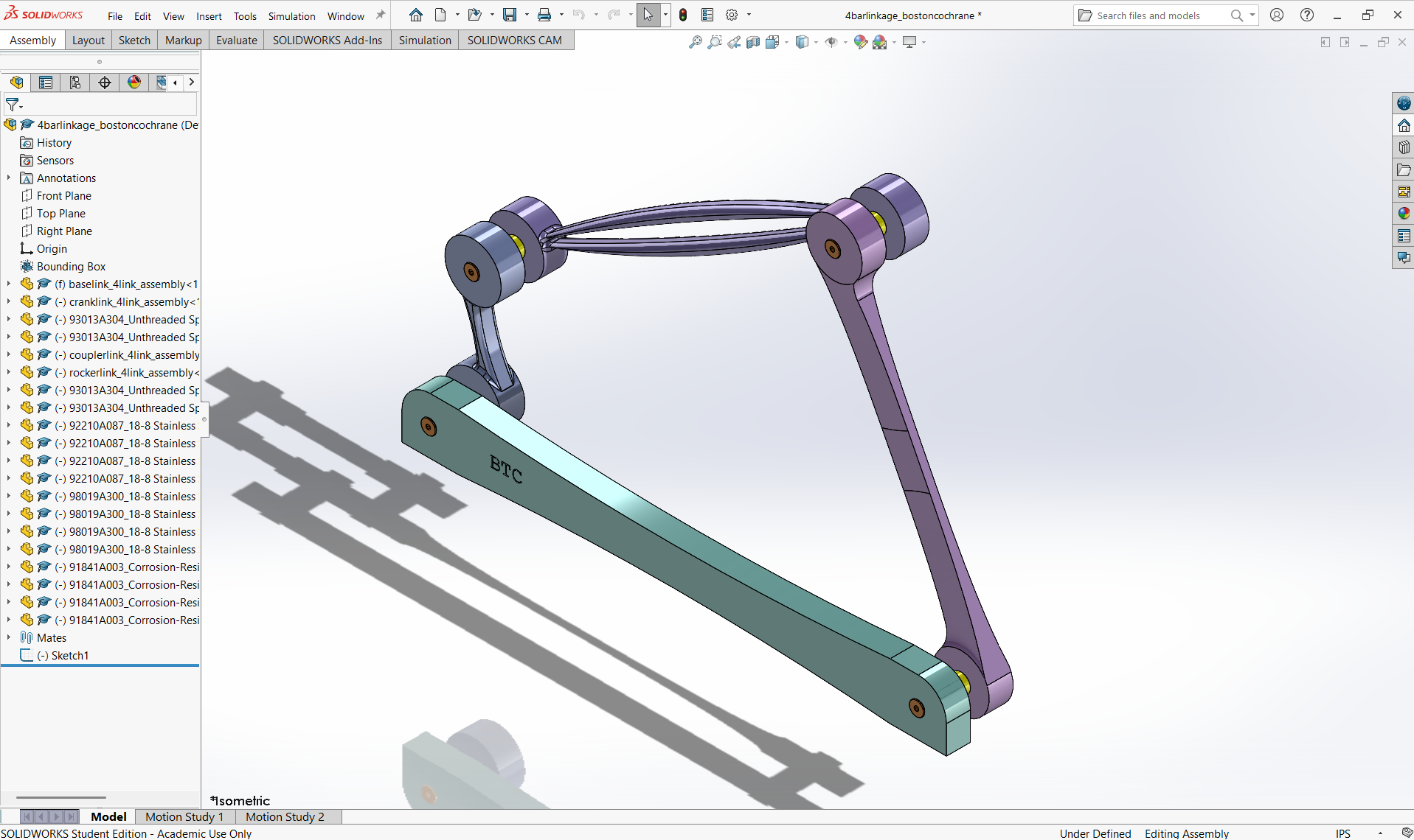
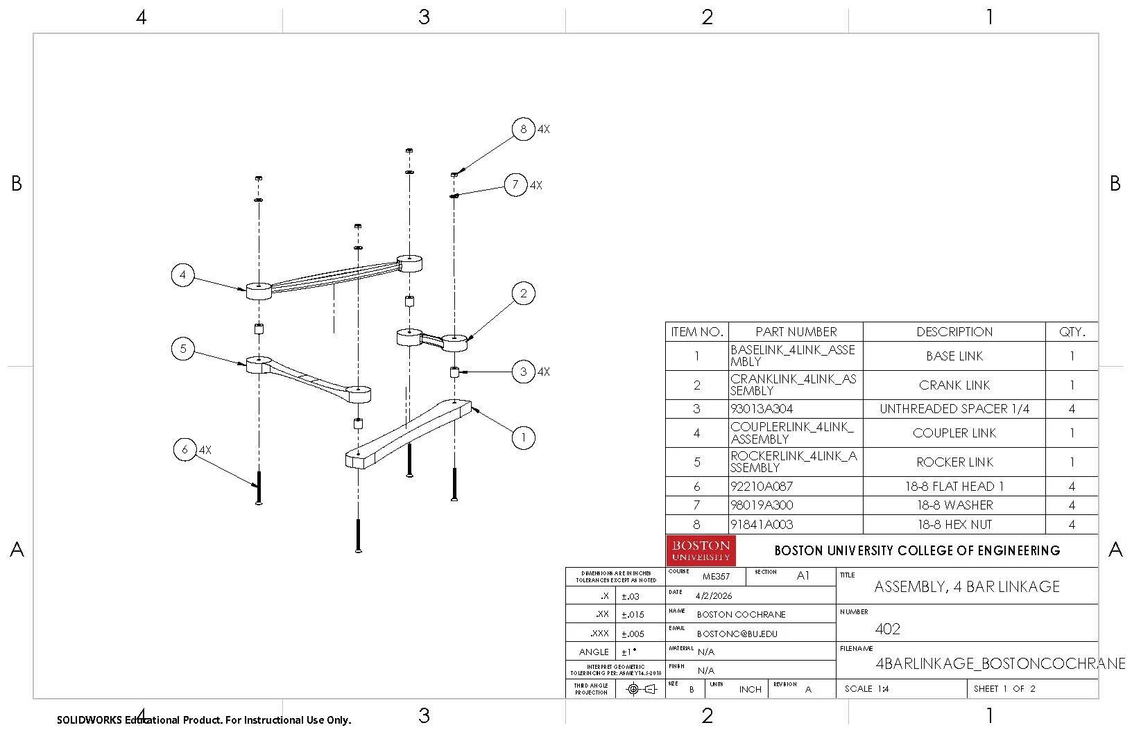
Then, the four bars were assembled with a chosen fastening system: a 18-8 stainless steel hex-drive flathead screw, a unthreaded spacer to allow free rotation, an 18-8 stainless steel hex nut, and an 18-8 stainless steel washer.
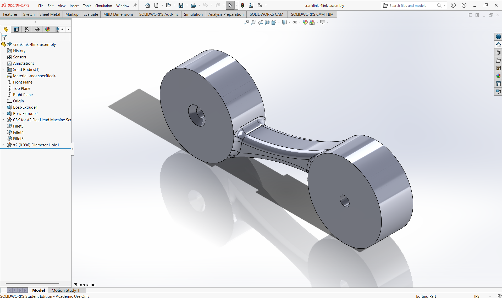
Crank link
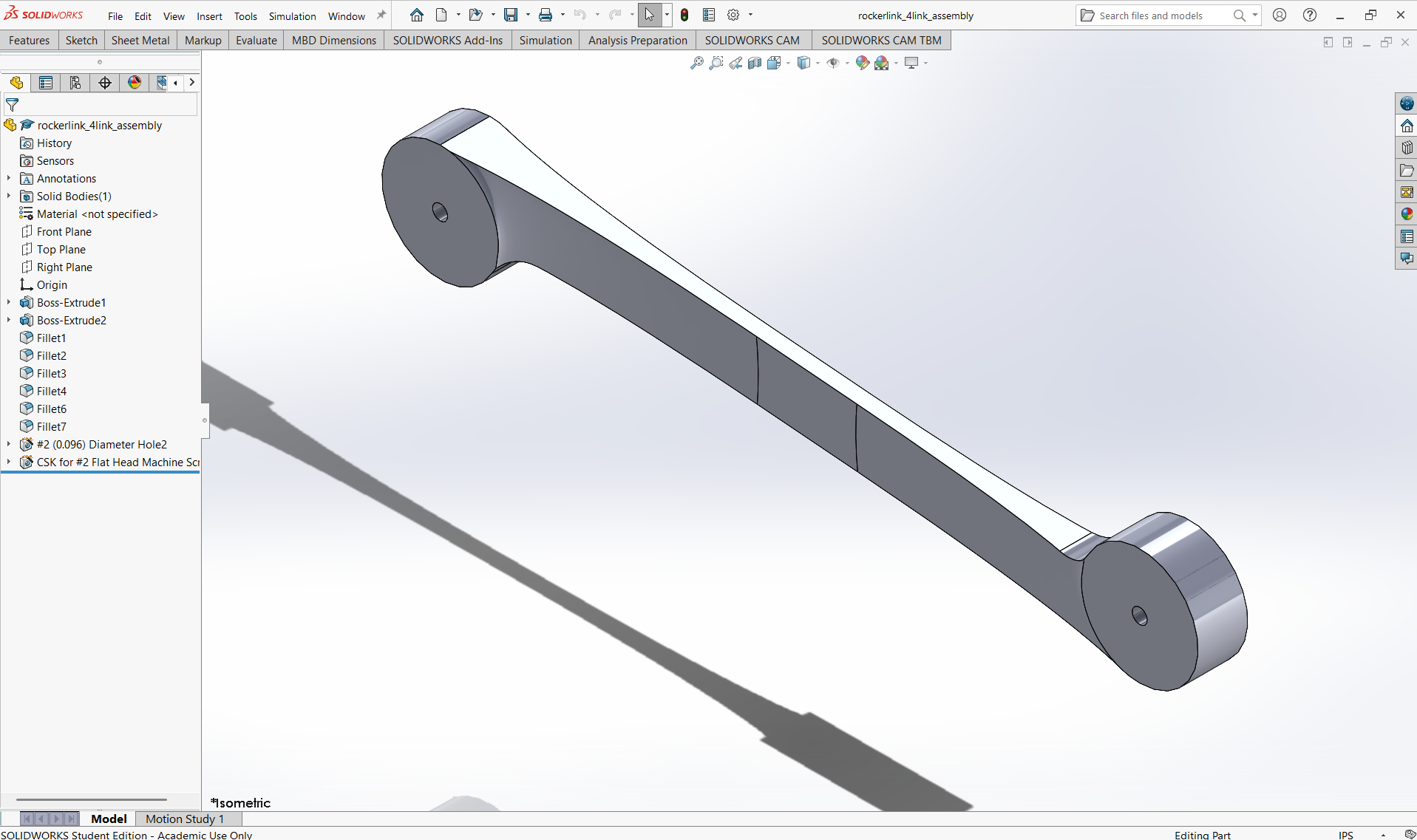
Rocker link
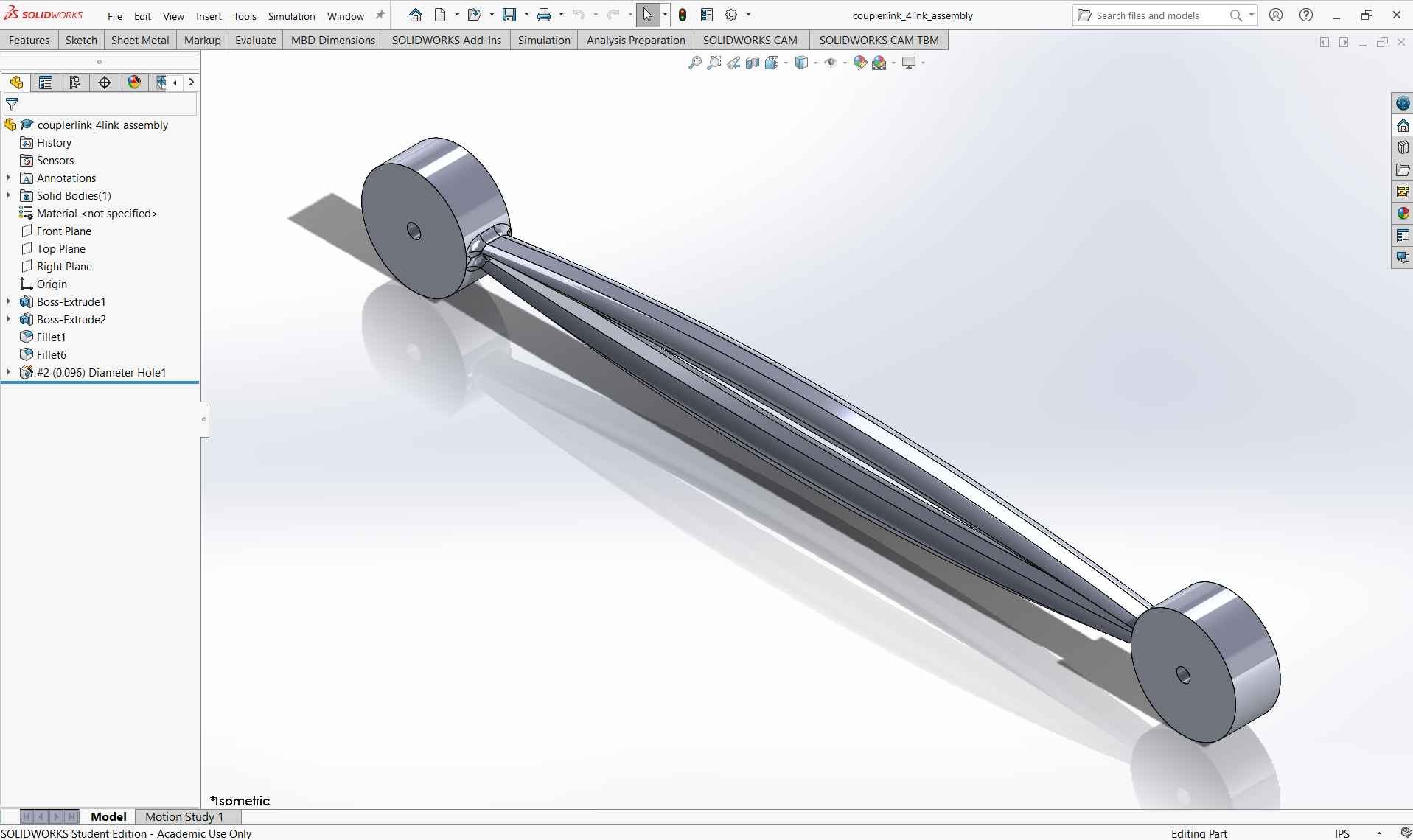
Coupler link
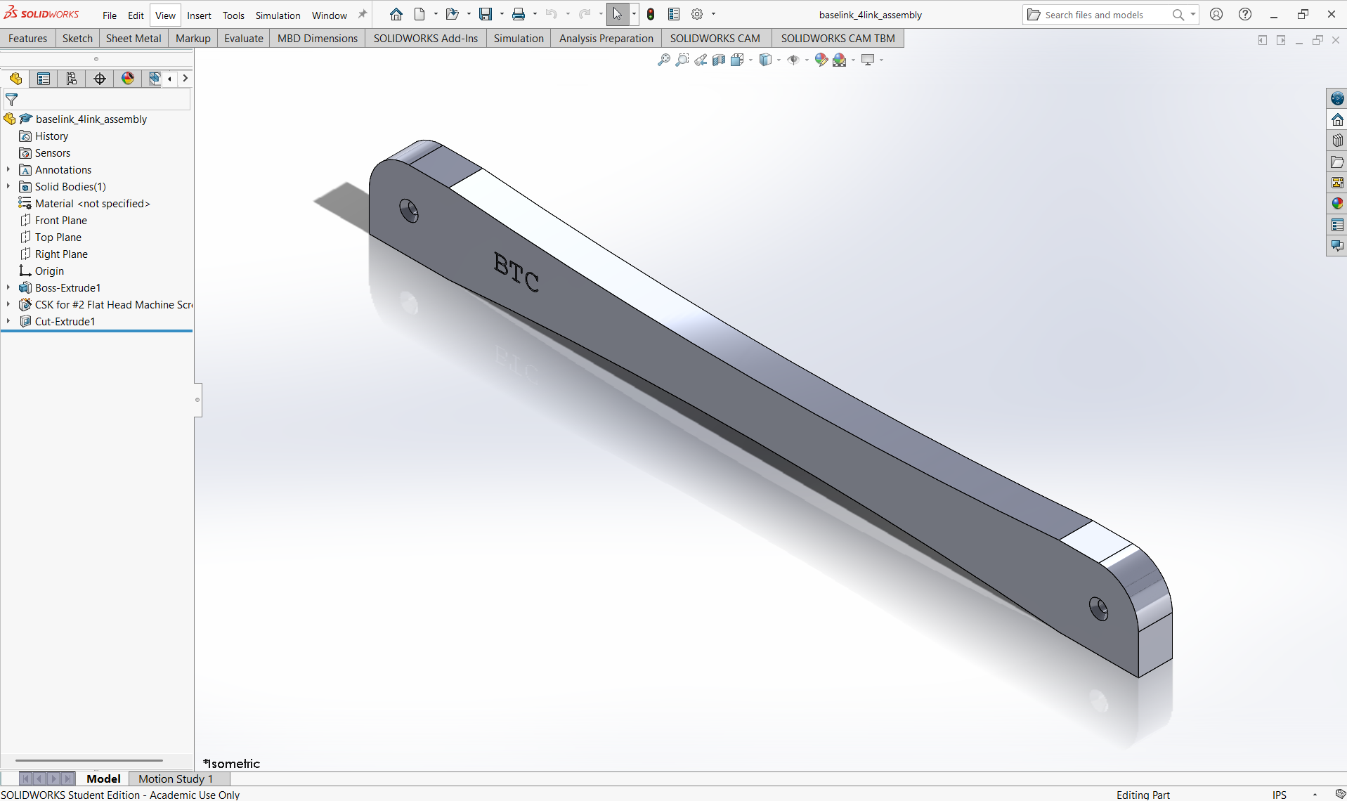
Base link
Results
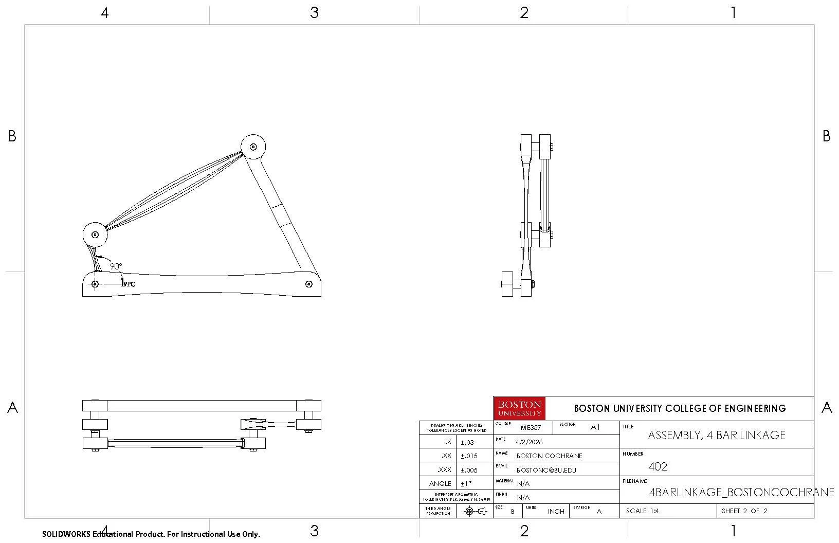
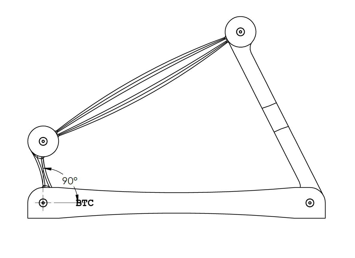
The final deliverables include two drawings, one representing complete assembly views and the other representing an exploded view to demonstrate the order of assembly, complete with a bill of materials to account for each unique part and its quantity.
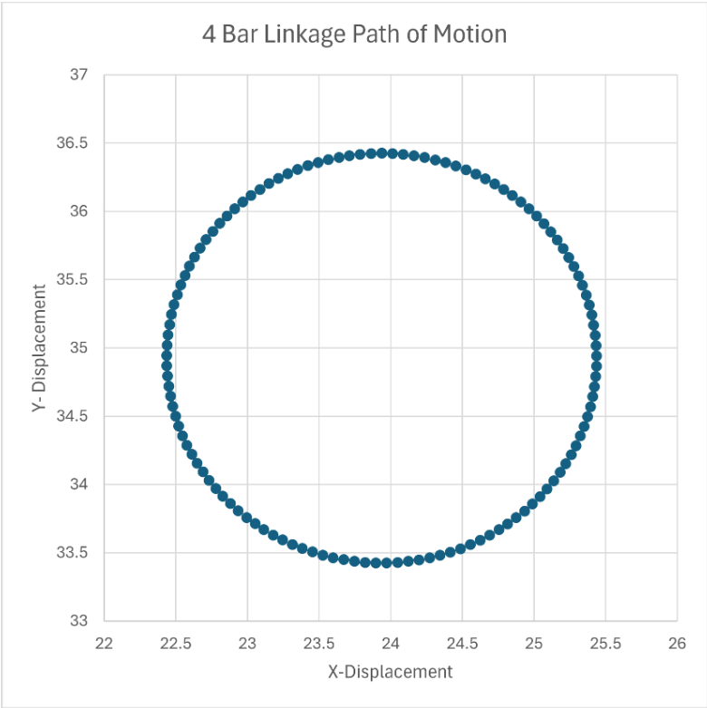
An animated motion study was also created, which includes the path of motion of the crank (also plotted as an x vs. y position graph) and the 8.5” x 11” allowed plane of motion.