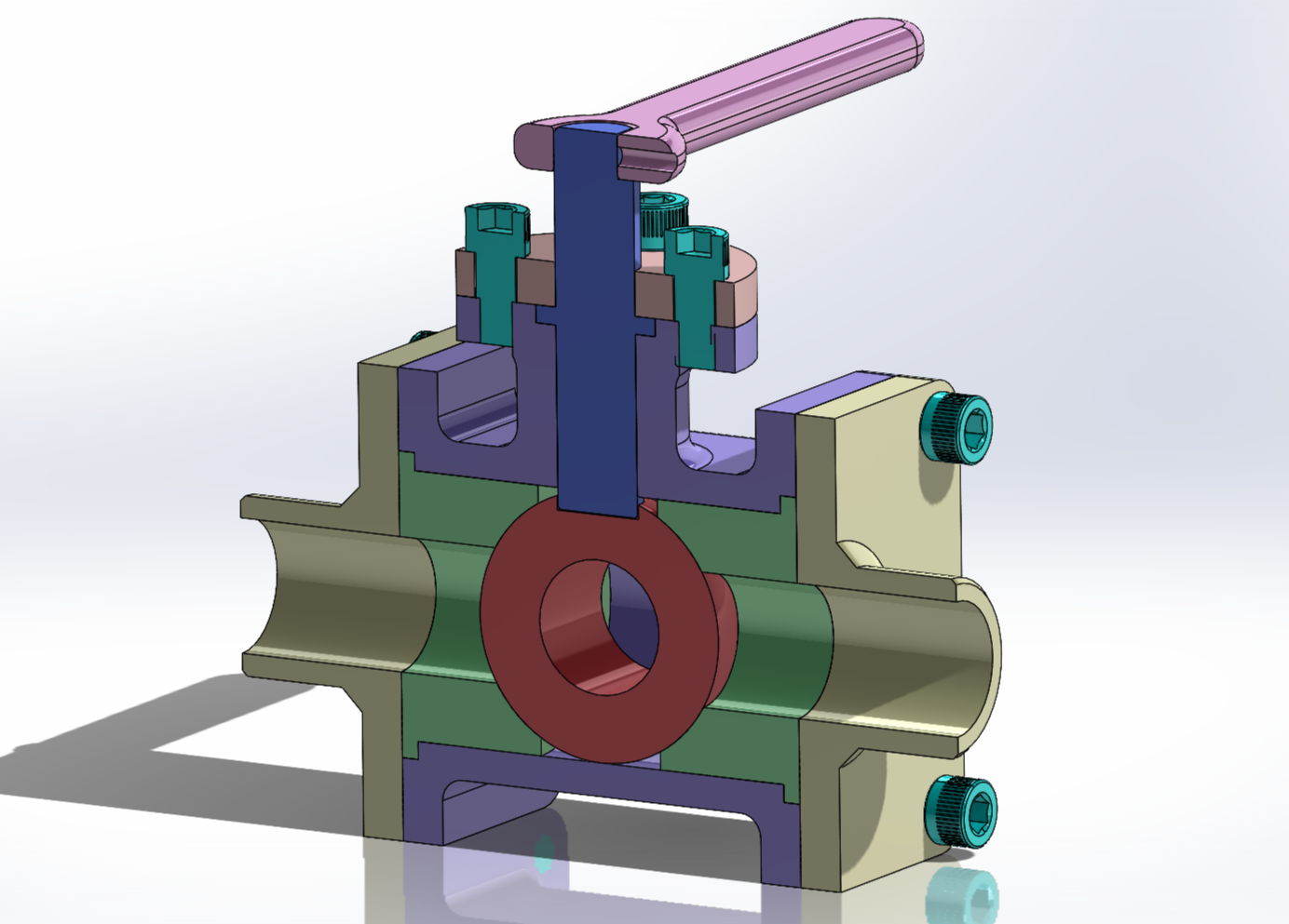
Ball Valve CAD
//CAD (SolidWorks)
Task
Model the ball, housing, reducer, and shaft for a ball valve given an engineering drawing for each and assemble with other provided components. Create an exploded view animation from the resulting assembly.
Design
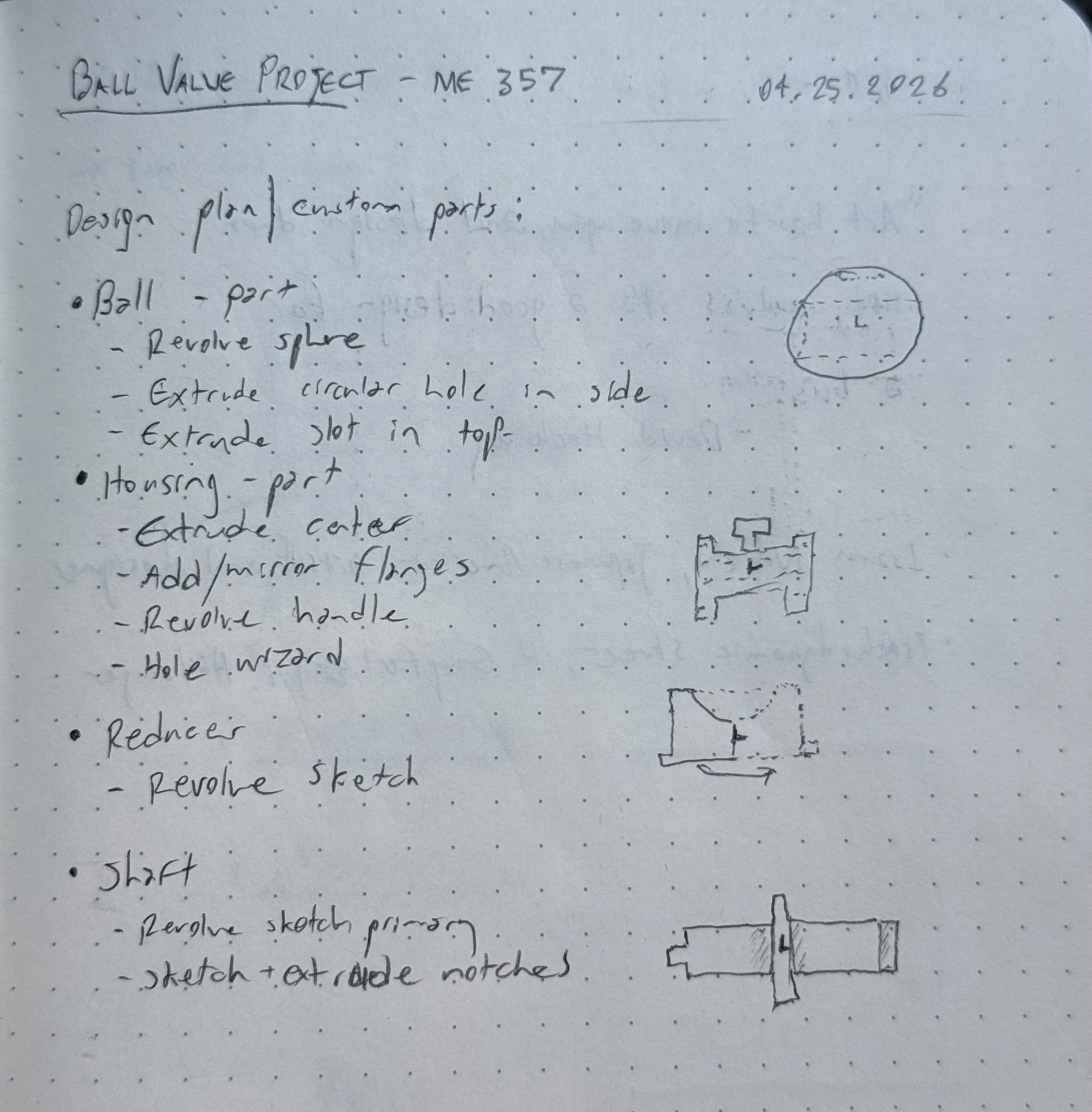
First, a rough plan was mapped up for the component modeling, including key features and the order in which they would be executed.
Then, each of the four components was modeled based on course-provided dimensioned engineering drawings.
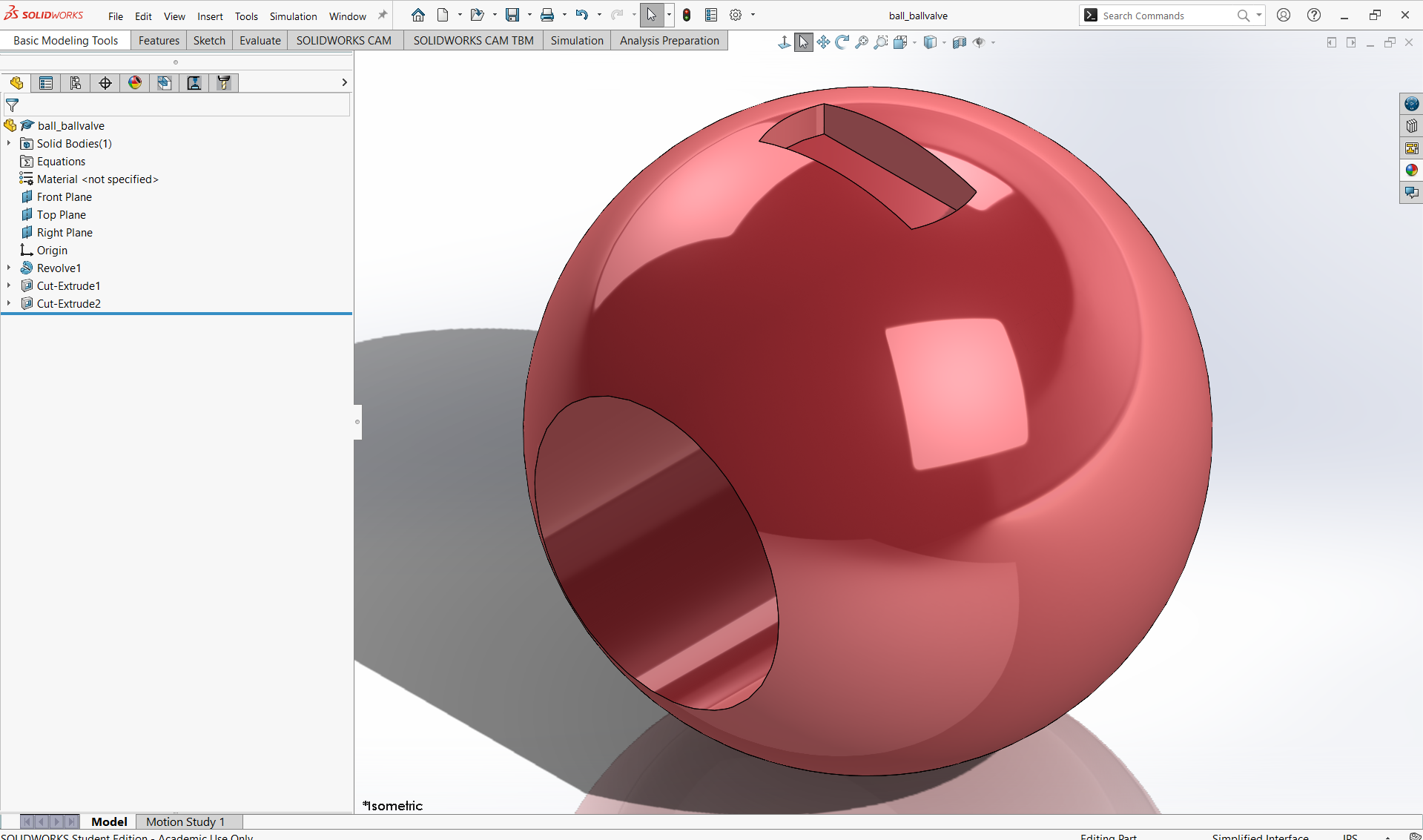
Ball
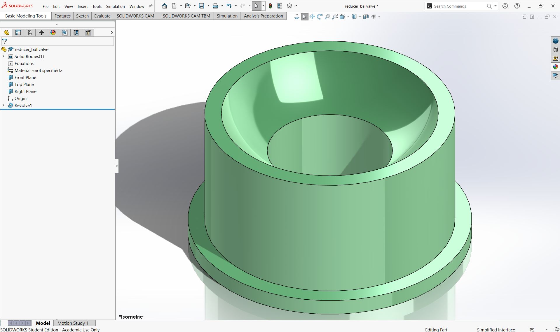
Reducer
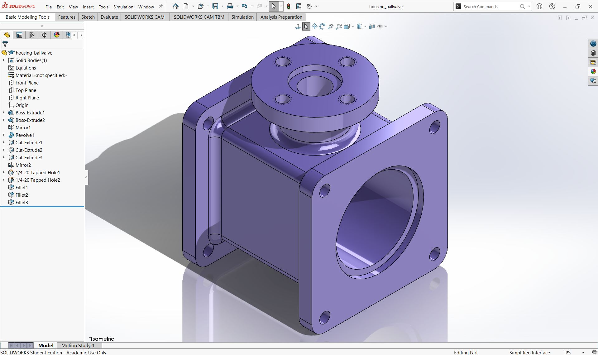
Housing
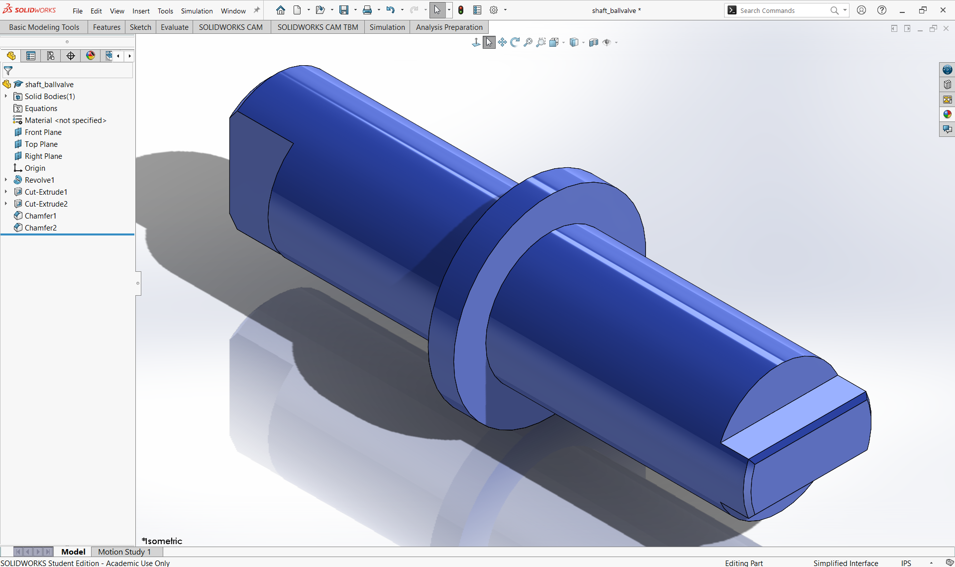
Shaft
Finally, the four modeled components were assembled with other course-provided parts, including fasteners, covers, and the handle, to make the complete ball valve system. Mates were assigned to make for appropriately restricted motion.
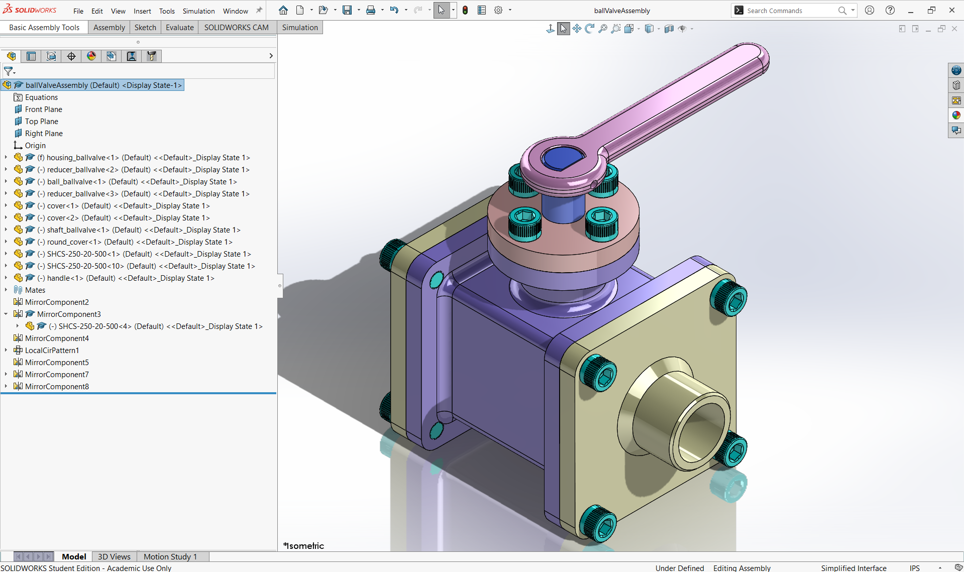
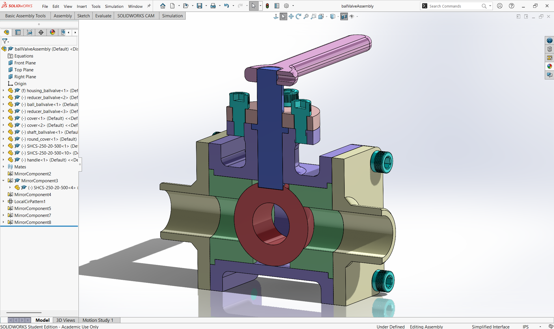
Results
An exploded view was created and animated from the final ball valve assembly to visually communicate the assembly process and showcase the components.